Overview
In this assignment we explored how different geometries can be represented on a computer. Building up from Bezier curves to 3D mesh modification, we learned how geometry can be mathematically defined and then modified. It was interesting to learn how a simple data structure like half edge can be used to encode complex relationships and perform modifications using only a few standard pointer assignments. Additionally, it was interesting to extend De Casteljau’s algorithm from Bezier curves to entire surfaces. As a whole, we ended up with a basic mesh processing and modification tool that can take in any input mesh, render it and then allow for changes like edge splits, flips and subdivision.
Part 1: Bezier Curves with 1D de Casteljau Subdivision
Screenshots - de Casteljau evaluation of our custom 6-point curve
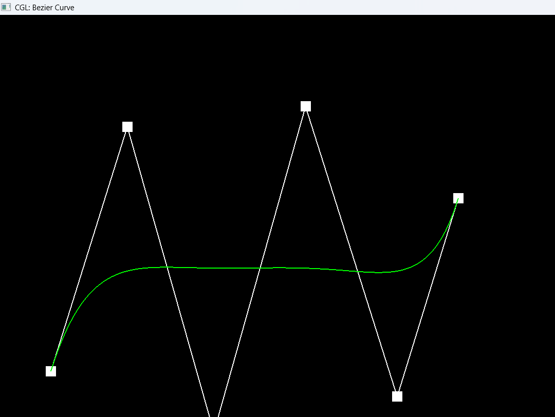
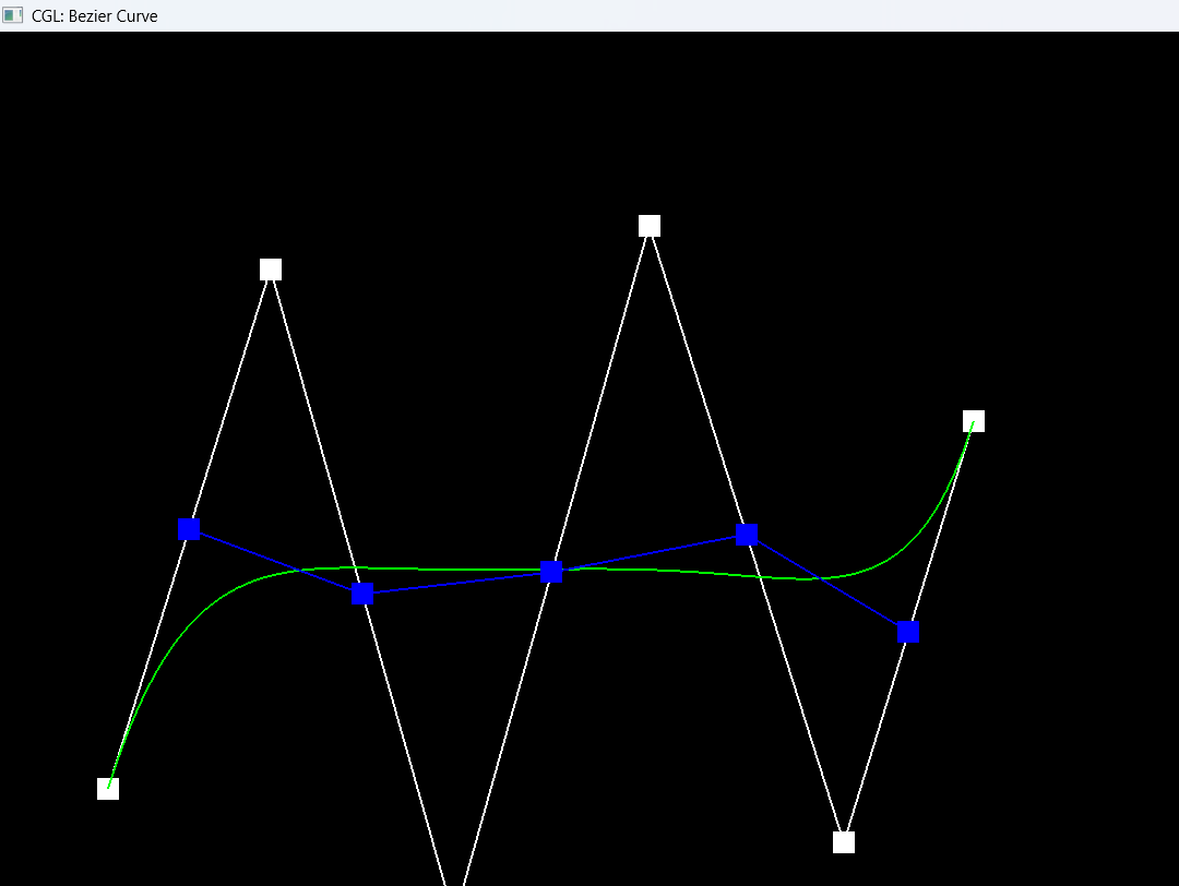
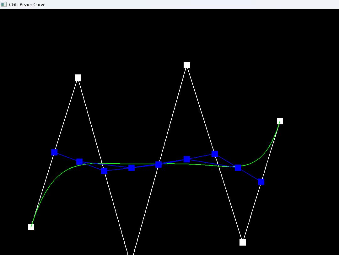
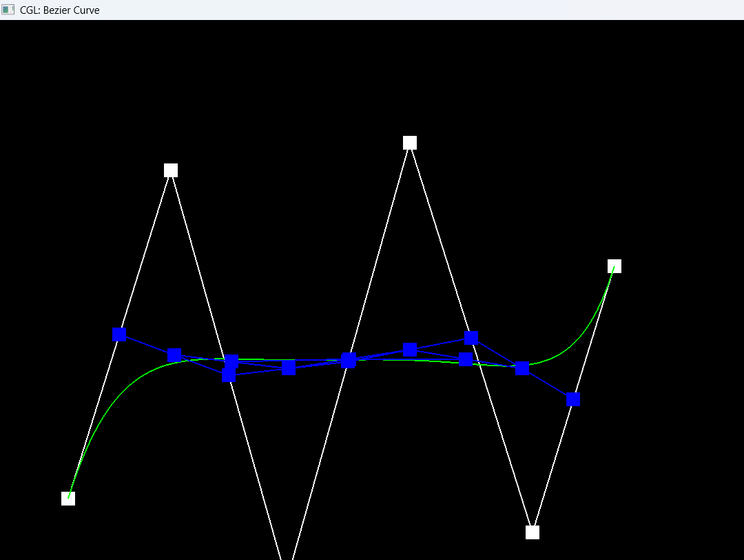
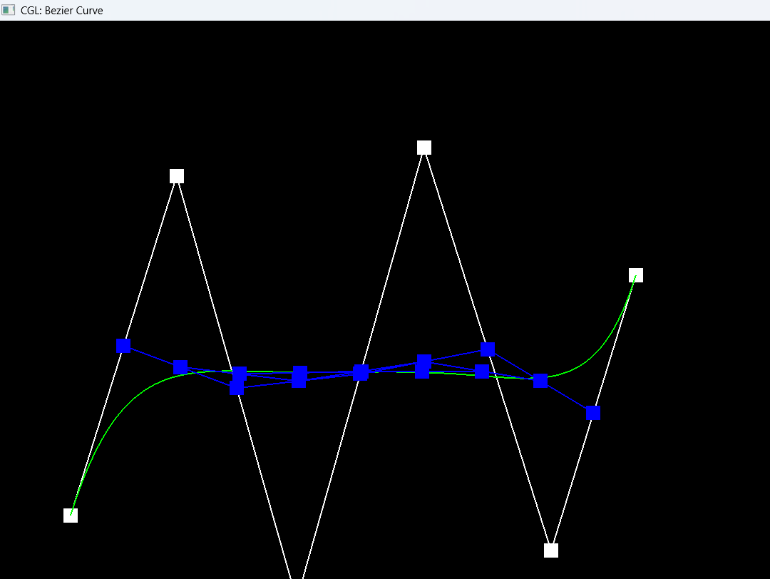
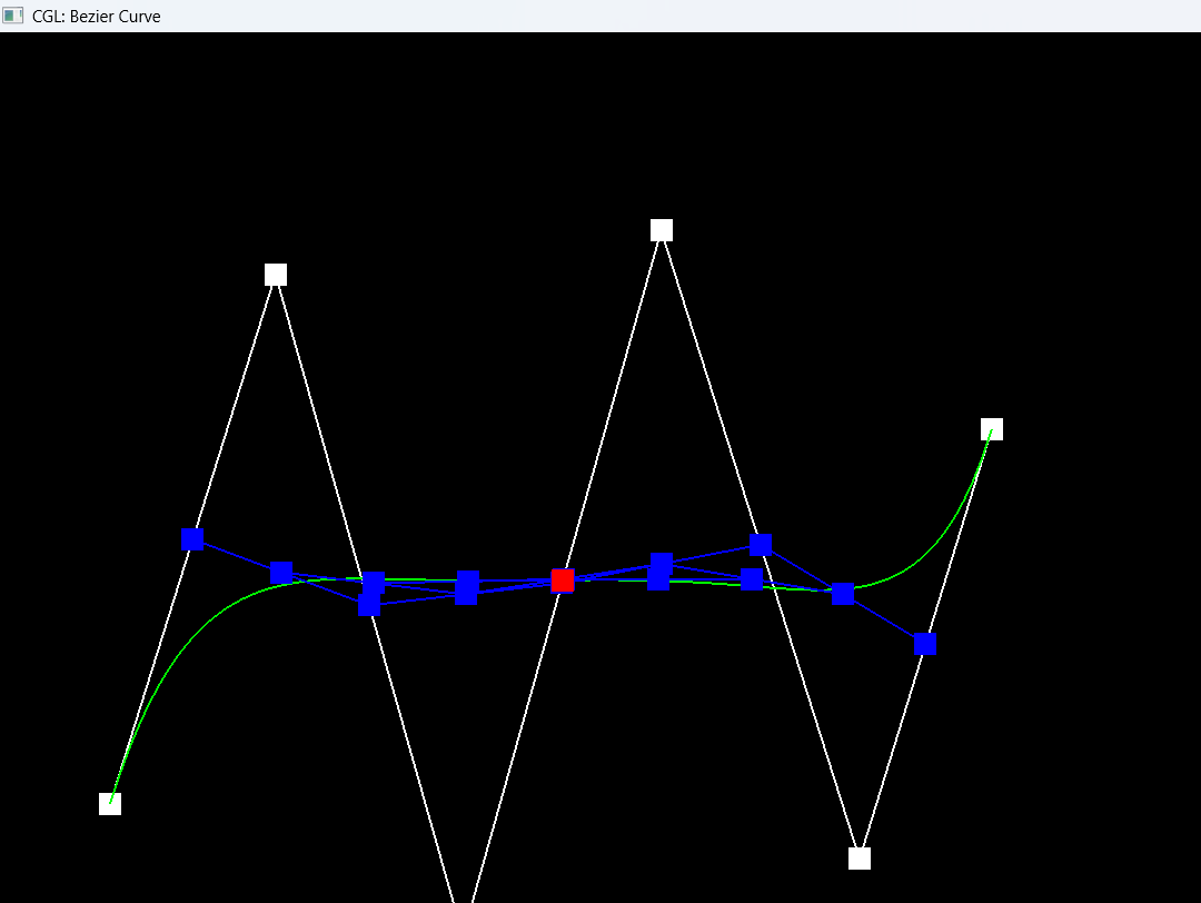
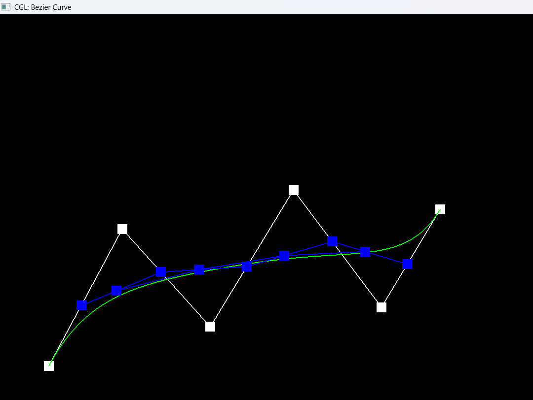
Explanation
A Bezier curve of degree n is defined by n+1 control points and a single parameter that ranges from 0 to 1, called t. To find the actual point on the curve, we use De Casteljau's algorithm. What it does is evaluate the curve through linear interpolation instead of plugging t into a big polynomial.
The core idea is a single recursive step. You start with k control points, and from those we produce k-1 new points, where each new point is the lerp of a consecutive pair at parameter t:
p_i' = (1 - t) * p_i + t * p_(i+1)
Every step shrinks the control polygon, so k becomes k-1, then k-2, and so on. Eventually we get down to a single point, and that point lies exactly on the Bezier curve at parameter t. Sweeping t from 0 to 1 and collecting these final points traces out the whole curve. For our six control point curve, that means the points go 6, 5, 4, 3, 2, 1, which is what is being shown in the screenshots above.
What we did is implement that single recursive step. BezierCurve::evaluateStep performs one level of subdivision. It takes a list of points and returns the next list, which is one point shorter.
std::vector<Vector2D> BezierCurve::evaluateStep(std::vector<Vector2D> const &points)
{
  std::vector<Vector2D> intermediates;
  for (size_t i = 0; i + 1 < points.size(); i++) {
    Vector2D lerped = (1.0f - t) * points[i] + t * points[i + 1];
    intermediates.push_back(lerped);
  }
  return intermediates;
}
Looking at the code, we loop over every adjacent pair of points using the condition i + 1 < points.size() so that we always have a valid pair, and we produce n-1 outputs from n inputs. For each pair we compute the lerp, where t is a BezierCurve class member that updates as we scroll the mouse. Pressing E advances the evaluation by one level, and that is how we created the level by level screenshots, and toggling C overlays the fully evaluated green curve.
Part 2: Bezier Surfaces with Separable 1D de Casteljau
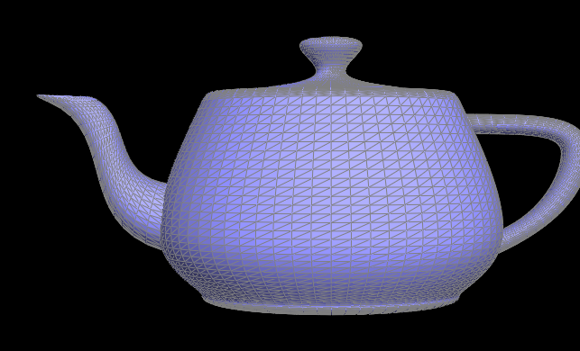
bez/teapot.bez evaluated by our implementation (each patch sampled over a grid of (u, v)).Explanation
For Part 2 we moved from curves to surfaces. A Bezier surface of degree (n, m) is defined by an (n+1) by (m+1) grid of control points, and instead of one parameter it uses two, u and v, both ranging from 0 to 1. The nice thing is that de Casteljau extends to surfaces in a separable way, which just means we run the same 1D algorithm from Part 1 twice.
The idea is this. First we look at each row of the control point grid on its own. Each row is just a set of control points, so it defines a 1D Bezier curve, and we evaluate that curve at u using the exact same de Casteljau steps from Part 1. That collapses each row down to a single point, so if there are n+1 rows we end up with n+1 points. Those points then act as the control points of one more Bezier curve, and we evaluate that curve at v to get the final single point that lies on the surface at (u, v). The viewer calls this for a whole grid of u and v values to build up the teapot mesh you see in the screenshot.
We split this into three functions. evaluateStep is the same one level of de Casteljau as before, except on 3D points and with t passed in as an argument, since we evaluate at both u and v and cannot use a single member t:
std::vector<Vector3D> BezierPatch::evaluateStep(std::vector<Vector3D> const &points, double t) const
{
  std::vector<Vector3D> val1;
  for (size_t i = 0; i + 1 < points.size(); i++) {
    val1.push_back((1.0 - t) * points[i] + t * points[i + 1]);
  }
  return val1;
}
evaluate1D takes a list of points and fully collapses it down to the single point on that curve at t, by calling evaluateStep over and over until only one point is left:
Vector3D BezierPatch::evaluate1D(std::vector<Vector3D> const &points, double t) const
{
  std::vector<Vector3D> val2 = points;
  while (val2.size() > 1) {
    val2 = evaluateStep(val2, t);
  }
  return val2[0];
}
evaluate(u, v) ties it together. It loops over every row of controlPoints, collapses each row at u with evaluate1D to get one point per row, and then collapses those points at v to get the final point on the surface:
Vector3D BezierPatch::evaluate(double u, double v) const
{
  std::vector<Vector3D> val3;
  for (size_t i = 0; i < controlPoints.size(); i++) {
    val3.push_back(evaluate1D(controlPoints[i], u));
  }
  return evaluate1D(val3, v);
}
Part 3: Area-Weighted Vertex Normals
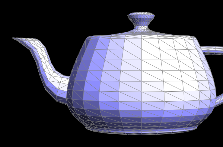
dae/teapot.dae with flat shading (per-face normals), before pressing Q.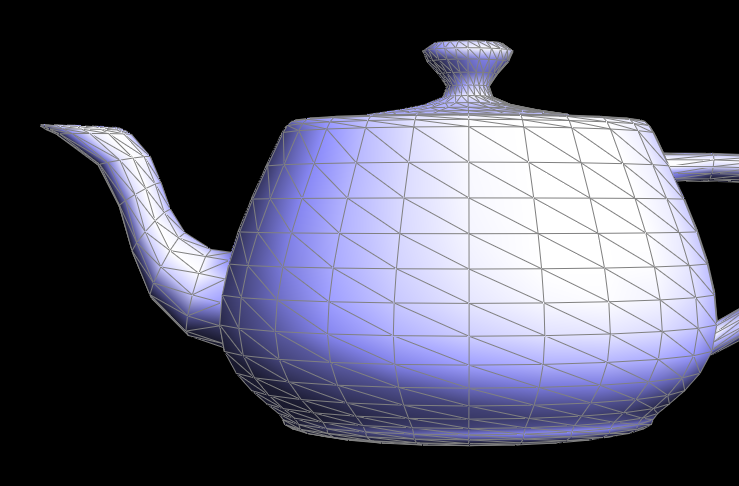
Explanation
For Part 3, what we are doing is computing a normal vector at each vertex of the mesh. A vertex normal is useful because it lets us do smooth shading instead of flat shading, so a coarse mesh looks rounded instead of faceted. In the viewer, pressing Q toggles between the two, and you can watch the teapot go from kind of blocky to smooth.
The way we get a good vertex normal is we look at all the triangles that touch the vertex, and then we average their face normals, weighting by area so that the bigger triangles have more influence. To do that we need to visit every triangle around the vertex, which is something the half-edge data structure makes easy.
So what we did is implement the vertex normal as a constant function, because it only reads the mesh and never changes it, so it uses the constant iterator type. We start at one half-edge rooted at the vertex and orbit around it using h->twin()->next(), which gives the next half-edge around the same vertex, and we keep going until we get back to where we started. For each half-edge we skip boundary faces, and for the real triangles we grab the other two vertices.
Now we need to weigh by area. For a triangle made of our vertex and its two neighbors, the cross product gives us a vector that points along the triangle's normal, and whose length is basically twice the area of the triangle. So all we have to do is add up the cross products over all the neighboring triangles, and the bigger triangles automatically contribute more. At the end we normalize the accumulated vector to get the unit normal.
Vector3D Vertex::normal( void ) const
{
  Vector3D normalSum(0., 0., 0.);
  Vector3D val1 = position;
  HalfedgeCIter h = halfedge();
  do {
    if (!h->face()->isBoundary()) {
      Vector3D val2 = h->next()->vertex()->position;
      Vector3D val3 = h->next()->next()->vertex()->position;
      Vector3D edge1 = val2 - val1;
      Vector3D edge2 = val3 - val1;
      Vector3D faceNormal = cross(edge1, edge2);
      normalSum += faceNormal;
    }
    h = h->twin()->next();
  } while (h != halfedge());
  return normalSum.unit();
}
Part 4: Edge Flip
The edge flip operation requires careful tracking of pointers. As advised in some of the assignment’s documentation, it is easy to lose track of all reassignments and also easy to misorder references. As a result, it was key to work through this problem methodically.
I started out by drawing the mesh before and after the edge flip operation, assigning arbitrary labels to each edge, vertex and face (the order didn’t matter because of the symmetry of the Halfedge data structure). Pictured below are the diagrams I referenced:
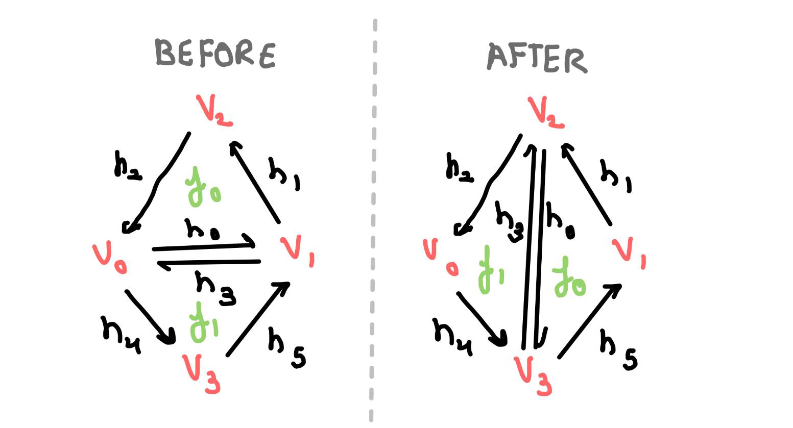
With this ordering in mind, figuring out the reassignments was much simpler. Following the assignment’s advice, I also reassigned every element, even if it didn’t need to be changed, to be on the safe side. The last step was implementing the pointer reassignments in a careful way (since the crux of this problem was just changing the mesh topology).
First, we check if the edge is a boundary, since in this case, a flip doesn’t really make sense (there is nothing to flip to):
// Immediately check for boundary first
if (e0->isBoundary()) {
    return e0;
}
Then, we get our two starting half edges as per the figure, h0 and h3:
HalfedgeIter h0 = e0->halfedge();
HalfedgeIter h3 = h0->twin();
Again, the order of these doesn’t matter since what really counts is the relative position of all the elements to each other. Having h0 and h3, I constructed references to every single mesh element to avoid losing a reference to them during reassignment:
HalfedgeIter h1 = h0->next();
HalfedgeIter h2 = h1->next();
HalfedgeIter h4 = h3->next();
HalfedgeIter h5 = h4->next();

VertexIter v0 = h0->vertex();
VertexIter v1 = h3->vertex();
VertexIter v2 = h2->vertex();
VertexIter v3 = h5->vertex();

FaceIter f0 = h0->face();
FaceIter f1 = h3->face(); // done getting all old pointers
Then, the last part of this assignment was systematically updating the pointers to come up with the “AFTER” diagram as shown above. Again, I reassigned every single pointer for simplicity (and the operation is still constant time). A few examples of the changes (not showing all for brevity):
// reassign all the halfedges next
h0->next() = h5;
h1->next() = h0;

// reassign all the vertices from half edges
h0->vertex() = v2;
h1->vertex() = v1;

// reassign faces for the half edges
h0->face() = f0;
h5->face() = f0;

// reassign half edges for the faces
f0->halfedge() = h0;
f1->halfedge() = h3;

// reassign half edges for the vertices
v0->halfedge() = h4;
v1->halfedge() = h1;
Due to the organization, I fortunately did not have to deal with much debugging since I was able to ensure visually that all the relevant points were reassigned correctly. Applying these edge flips to the teapot:
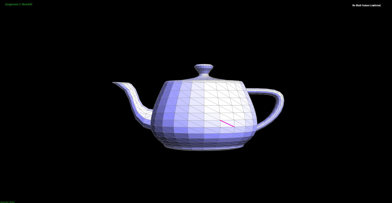
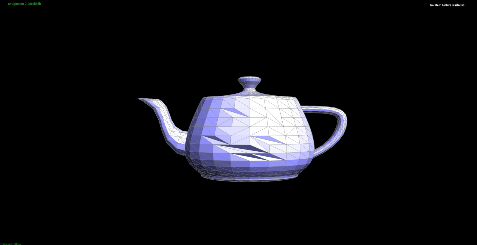
It is interesting to see how flipping some of the edge can cause indentations in the geometry since the mesh topology is not fine enough to represent the needed curvature.
Part 5: Edge Split
I followed a similar method as I did to part 4 to ensure I did not lose track of any pointers. Again for the sake of simplicity, I reassigned every pointer even if it was not required - the split operation is still constant time.
Starting with the before and after sketches, with features arbitrarily, but consistently labelled:
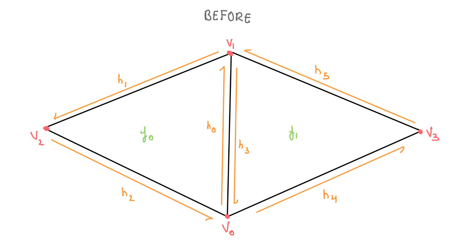
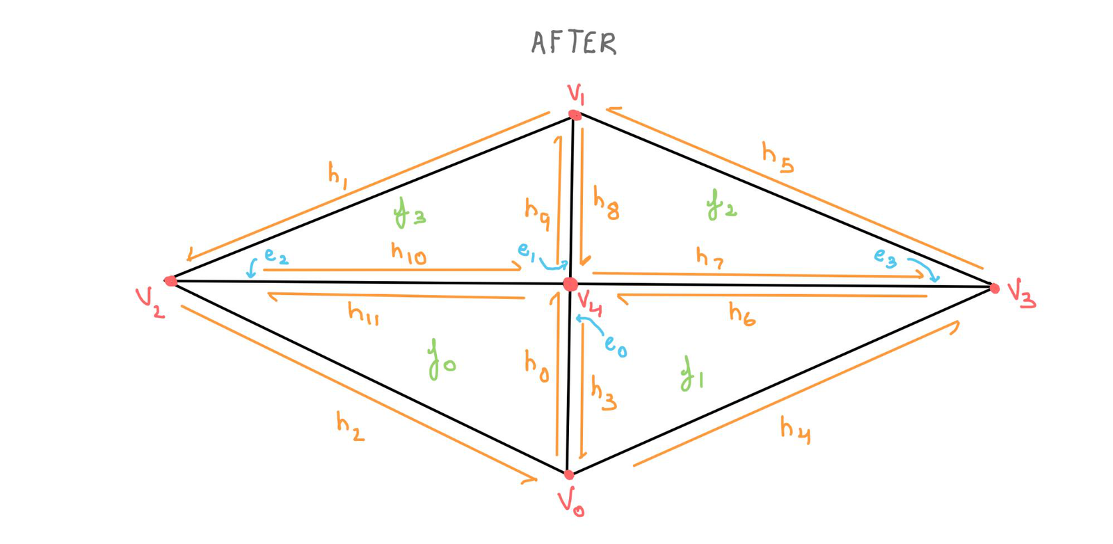
These served as a good frame of reference when doing the pointer reassignments to change the mesh topology to represent that of a split edge. The overall process was similar to that for edge flip, except that the split created 3 new edges (6 new halfedges), one new vertex and 2 new faces. Each of these had to be created and then made to reference the correct elements.
Again, we start by checking if the edge is a boundary as we did in part 4. If it is not a boundary, we proceed with the splitting operation. Just as before, we create references to all the ‘old’ halfedges, faces and vertices. The code for this was the same as it was in part 4.
Then, we need to create references to the new vertex v4 and to all the new edges, halfedges, and faces. This is done using the corresponding functions defined in the Halfedge primer as follows (labelled as they would be in the diagram to not lose track):
VertexIter v4 = newVertex();

EdgeIter e1 = newEdge();
EdgeIter e2 = newEdge();
EdgeIter e3 = newEdge();

FaceIter f2 = newFace();
FaceIter f3 = newFace();

HalfedgeIter h6 = newHalfedge();
HalfedgeIter h7 = newHalfedge();
HalfedgeIter h8 = newHalfedge();
HalfedgeIter h9 = newHalfedge();
HalfedgeIter h10 = newHalfedge();
HalfedgeIter h11 = newHalfedge();
Next, we can assign the position of vertex v4 to be the midpoint of v0 and v1:
// new vertex position is in the middle (average of v0 and v1)
v4->position = 0.5*(v0->position + v1->position);
With that, we can start with all the pointer reassignments. To ensure that I would not get lost, I did these by element type, in the following order: assign all halfedges’ next, assign all halfedge’s vertices, assign all the halfedge’s faces, assign all the halfedge’s corresponding edges, assign all the halfedge’s twin, assign all face pointers to a corresponding halfedge, assign all edges to a corresponding halfedge, assign all vertex pointers to their relevant halfedges. Going through the process in this way made it easy to focus on one type of element at a time. Finally we return v4 since that is the new vertex that defines the way the splitting works. Some examples of the assignments are shown below, but most are omitted for brevity:
// reassign all the halfedge's next
h0->next() = h11;

// reassign all the halfedge's vertex
h0->vertex() = v0;
h1->vertex() = v1;

// reassign all faces
h0->face() = f0;
h11->face() = f0;

// reassign all the halfedge's edge
h0->edge() = e0;
h3->edge() = e0;

// reassign all the halfedge's twin (pairs grouped together)
h0->twin() = h3;
h3->twin() = h0;

// reassign face pointers
f0->halfedge() = h0;
f1->halfedge() = h3;

// make edges point to halfedges
e0->halfedge() = h0;
e1->halfedge() = h8;

// make vertices point to halfedges
v0->halfedge() = h0;
Thanks to the organization, I faced few challenges in terms of debugging. The only major problem I had was that I had written the updated vertex position incorrectly as v4->position = 0.5*(v0->position - v1->position). Still this was easy to spot since the split operation did not produce the expected result at all as shown below:
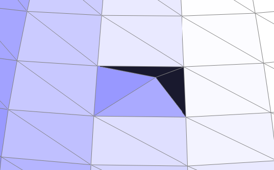
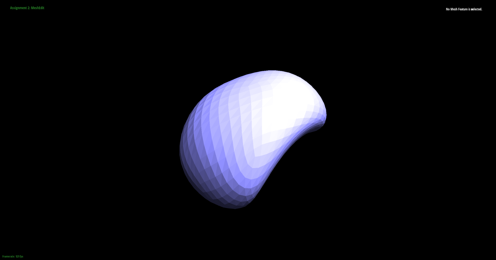
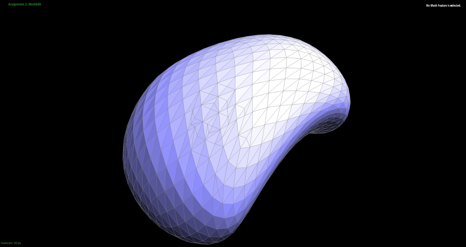
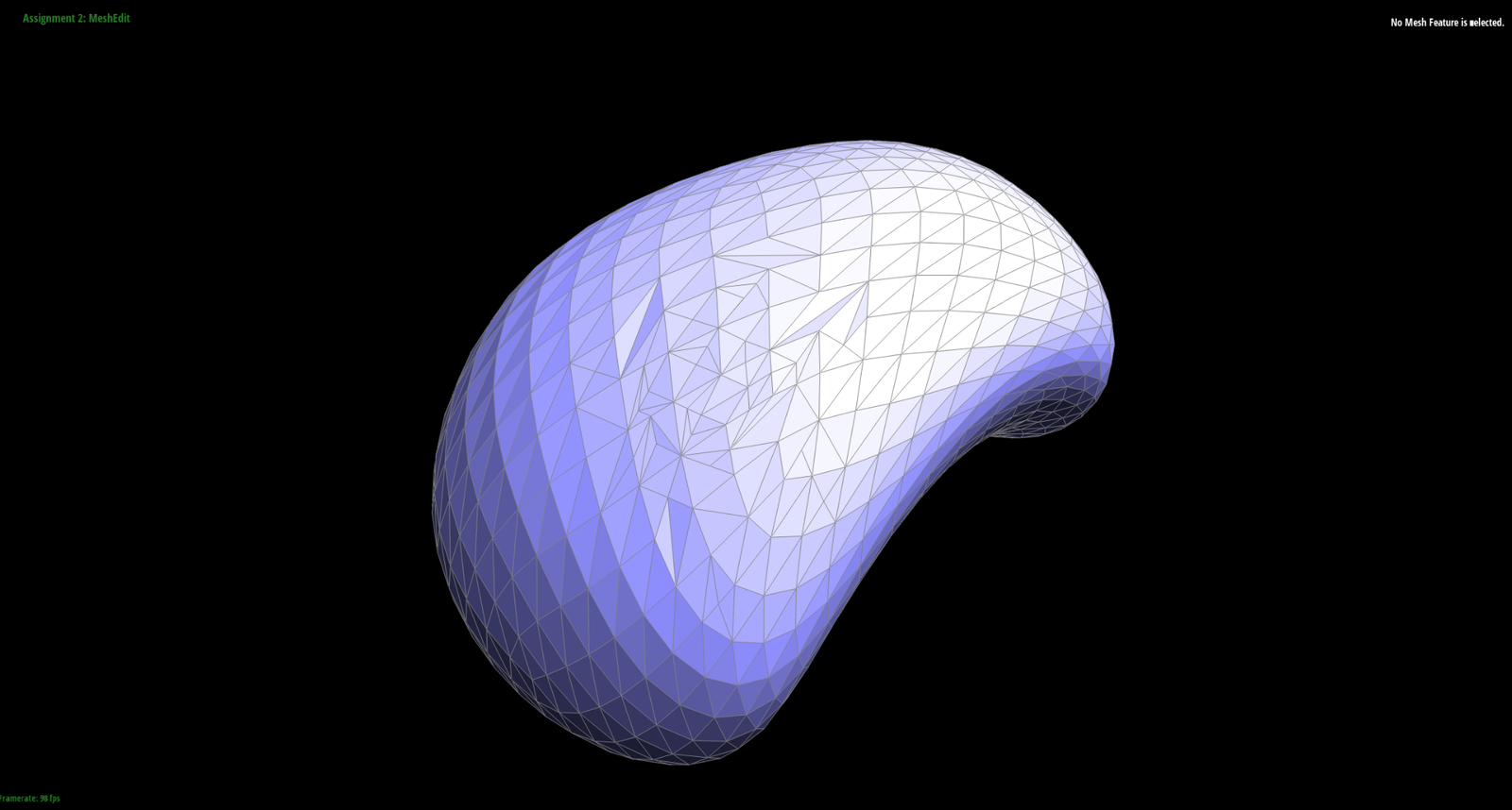
Applying these edge splits to the bean, we get the following results:
Part 6: Loop Subdivision
To implement loop subdivision, I followed the template given in the student_code file. The key idea was to define all the new vertex positions, store away all the possible updated old vertex positions, split every edge in the mesh, flip any newly split edges that connect a new and an old vertex and lastly copy the new and old vertex positions into each vertex’s position attribute. Looking at the code step by step:
1) Compute the updated positions of all the vertices as if they were the ‘old’ vertices shown in the project spec:
First, we loop over all the vertices and state that they are not new.
for (VertexIter v = mesh.verticesBegin(); v != mesh.verticesEnd(); v++) {
    v->isNew = false; // since we haven't updated, make all of them not new
Then, we find the vertex degree and the sum of all the neighbouring vertex positions by looping over all the surrounding vertices. I used similar code to that used to define v->degree().
double n = 0.0; // could have used v->degree() but need to walk around to get neighbour sum anyway
Vector3D neighbourSum(0.0, 0.0, 0.0);

HalfedgeIter h = v->halfedge();
do {
        neighbourSum = neighbourSum + h->twin()->vertex()->position; // add the position of the neighbour vertex
        n++;
        h = h->twin()->next();
} while (h != v->halfedge());
Lastly, we need to find u which is dependent on the vertex degree as given in the project spec. We can achieve this conditionality with an if statement and then use the value of u to update the new position of v, keeping the old one’s reference still intact:
double u = 0.0; // just initialize it first
if (n == 3.0) {
    u = 3.0 / 16.0;
} else {
    u = 3.0 / (8.0 * n);
}
v->newPosition = (1.0 - (n * u)) * v->position + u * neighbourSum; // important to use newPosition to not dereference
2) Next, we can compute the updated vertex positions associated with each edge as follows:
for (EdgeIter e = mesh.edgesBegin(); e != mesh.edgesEnd(); e++) {

    e->isNew = false; // all current edges are old

    HalfedgeIter h0 = e->halfedge();
    HalfedgeIter h0_twin = h0->twin(); // to get all required vertices

    Vector3D A = h0->vertex()->position; // first vertex of the edge
    Vector3D B = h0_twin->vertex()->position; // second vertex of the edge
    Vector3D C = h0->next()->next()->vertex()->position; // first adjacent vertex
    Vector3D D = h0_twin->next()->next()->vertex()->position; // second adjacent vertex

    e->newPosition = (3.0 / 8.0) * (A + B) + (1.0 / 8.0) * (C + D); // all in decimals to be safe
}
Overall, we loop over every single edge in the mesh and set it to be an old mesh. Then we find the two edge vertices and the two adjacent vertices (following the convention given in the project spec). Lastly, we assign the required weights to get the position of the ‘midpoint’ associated with that edge. We assign this vector value to the new position of the edge to make sure we don’t lose reference.
Now that we have all the hypothetical new positions, we just have to split the edges and then determine which ones connect a new vertex to an old one. Looping over all the original edges using a counter to ensure no repetition and storing the currently looped over edge’s reference before modifying it:
int originalEdgeCount = mesh.nEdges(); // as defined in halfEdgeMesh.h

EdgeIter e = mesh.edgesBegin();

for (int i = 0; i < originalEdgeCount; i++) { // do it this way to make sure we don't use a wrong reference
    EdgeIter nextEdge = e;
    nextEdge++; // store the next edge to change
We can find the two vertices associated with the edge before the split (since they will be harder to acquire after the split happens):
VertexIter v0 = e->halfedge()->vertex();
VertexIter v1 = e->halfedge()->twin()->vertex();
Then we can split the edge to create three new edges as was the case in part 5. This generates a VertexIter which points to a new vertex, and so we set this property:
VertexIter m = mesh.splitEdge(e); // this generates 3 new edges
m->isNew = true; // mark the new vertex as new
And then, we can set the position of this new vertex to be the one we found above (since this uses the correct weights):
m->newPosition = e->newPosition; // set the new vertex position to the value computed above
Lastly, we go over all the surrounding vertices of m and see if they were newly added, or if we just split an edge that was defined by v0 and v1. This is done by iterating systematically around the halfedge that the new vertex points to. If we are on an old edge, we reassign the isNew property to make sure this doesn’t get flipped later:
HalfedgeIter hm = m->halfedge(); // now we go over the surrounding vertices and see if they are old or new
do {
            VertexIter adj = hm->twin()->vertex();

            if (adj == v0 || adj == v1) { // if it's on the old edge don't reconsider (black edges in picture)
                hm->edge()->isNew = false;
            }
            else {
                hm->edge()->isNew = true; // this is not a black edge in the picture
            }

            hm = hm->twin()->next(); // now go to the next new edge that was created
        } while (hm != m->halfedge());

        e = nextEdge; // consider the next edge in the mesh
}
3) With all the possible splits done and the new edges distinctly marked, we can go over all the edges in the mesh and if the edge is new and it connects a new vertex to an old one, we flip it:
if (e->isNew && (((h->vertex()->isNew) && !(h_twin->vertex()->isNew)) ||
            (!(h->vertex()->isNew) && (h_twin->vertex()->isNew)))) {
            mesh.flipEdge(e);
}
4) The isNew parameter does not have to be updated because we do that at the beginning while precomputing all the new vertex and edge positions. Lastly, we can write the new vertex positions to all the vertices in the mesh by looping over them:
for (VertexIter v = mesh.verticesBegin(); v != mesh.verticesEnd(); v++) {
        v->position = v->newPosition;
}
Upon loop subdivision, any sharp corners get rounded out. For instance, when the cube file is repeatedly subdivided, it turns into a lopsided blob:
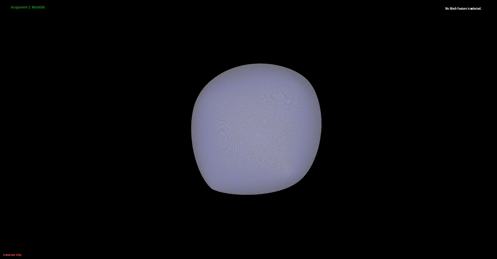
Notably, the lopsidedness likely occurs because the mesh topology is not symmetric (all the faces have a single diagonal across them which means that upon loop subdivision, the two triangles kind of stretch away from each other as the screenshot above shows). However, if we split every single face and then perform loop subdivision, we get a more perfect sphere because the subdivision rules get applied evenly across the mesh:
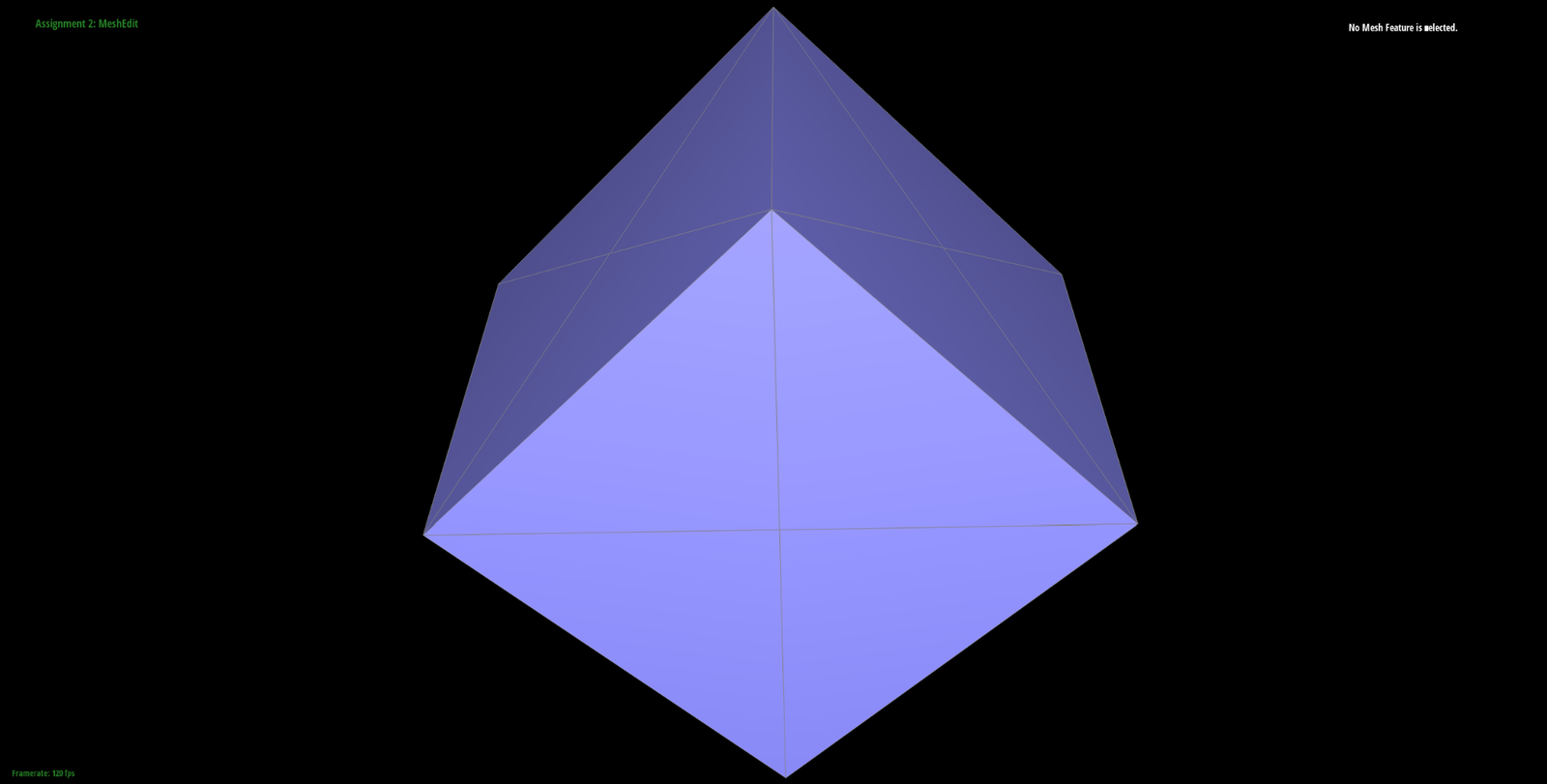
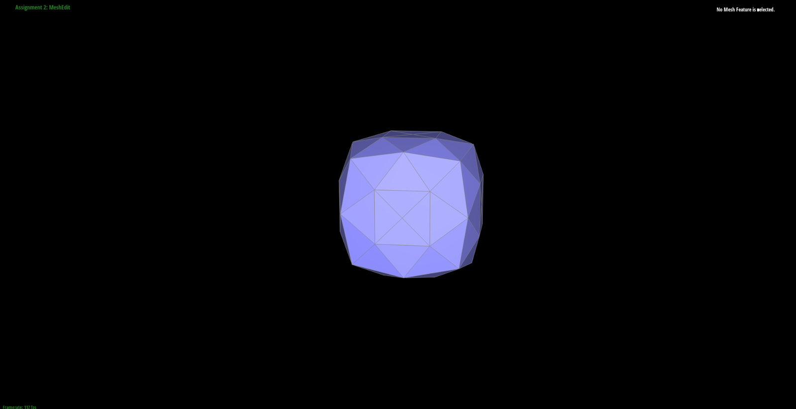
To avoid smoothing out edges and preserve some sharpness, we can perform edge splits along the boundary. For instance, without the splits, the teapot subdivides into (after one level of subdivision - Notice the smooth top edge):
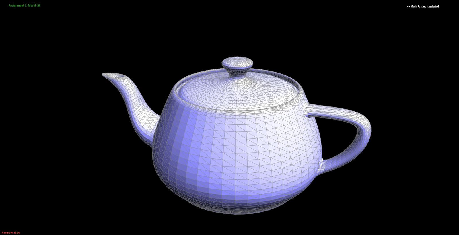
Instead if we perform some edge splits along that boundary to reduce the area over with loop subdivision can provide smoothing:
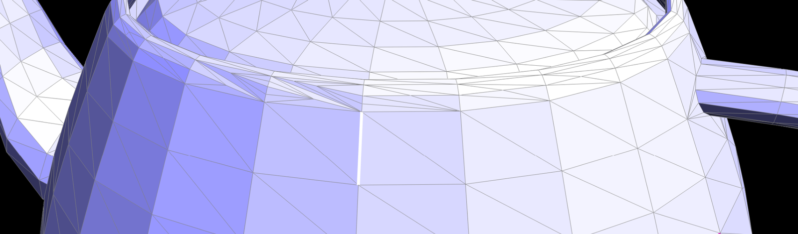
We get (turned off the grid for better visualization):
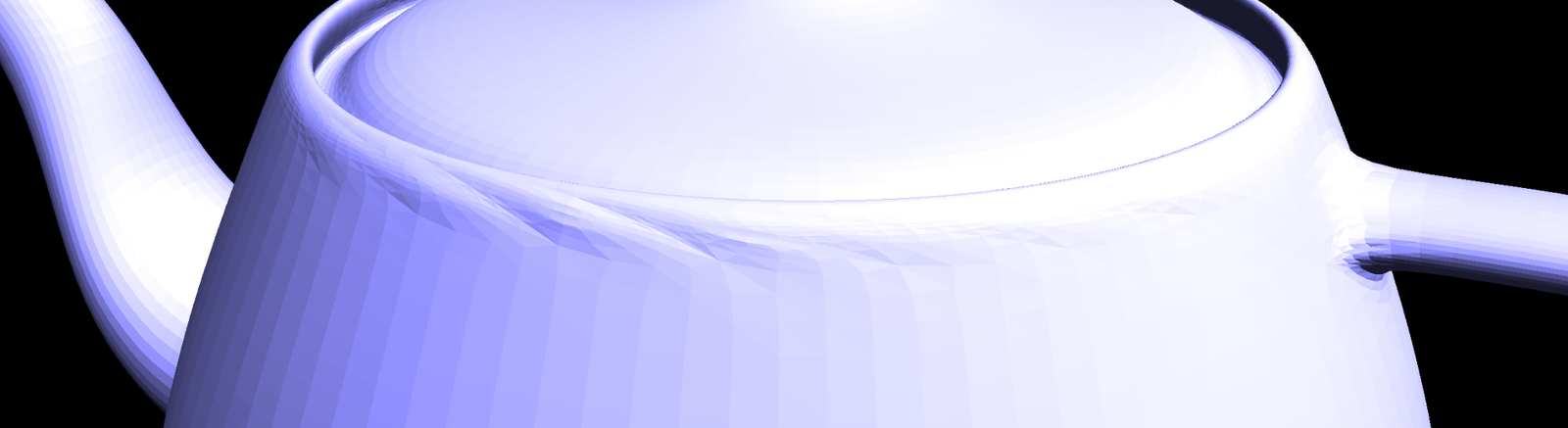
Notice the distinct creases which remain along the biased long edges. The image was taken at two levels of loop subdivision this time.